I recently blogged about my efforts to replace most of the bulbs in my Fiesta with LEDs. Mostly this has gone well, but one area where there have been difficulties are the indicators.
When I installed the first LED I immediately got “hyperflash” where the flash rate increases a great deal to practically produce a flickering effect. My supplier – Classic Car LEDs – had indeed predicted this problem and investigating and solving it taught me a great deal about how indicators work.
Clearly, hyperflash is a response to the much smaller current consumed by the LED lamps. Naively, I had supposed that this was a result of the smaller current affecting the operation of the bimetallic strip based flasher units of yore. I was therefore surprised that it would affect a relatively modern flasher unit like mine from 1997. However, I was completely missing the point.
Whilst ancient flasher units might have flashed faster due to different heating of the bimetallic strip (or possibly wouldn’t have flashed at all) modern electronic flashers actually deliberately introduce this effect to alert the driver to a failed bulb. It is therefore an early version of the CANBUS mechanism on more modern vehicles.
Classic Car LEDs offered two basic solutions to the problem which both boiled down to using resistors to get the current back to what it was. Either the LEDs could be replaced by ones containing suitable resistors or separate “ballast” resistors could be added to the wiring.
The other possible solution of fitting a new flasher unit which wouldn’t exhibit hyperflash was apparently not possible as the Mk4 uses a rare type of flasher. However, when I removed the flasher unit it seemed exactly like the ones on offer so far as I could see.
I briefly toyed with making my own flasher, but then spent some more time looking into the problem online. I discovered that nearly all modern flasher units use the venerable U643B chip. This uses a low value shunt resistor to measure the bulb current and several people pointed out that simply disconnecting the current sense pin (7) solved the hyperflash problem.
I removed the flasher from the car. This is a little more complex than on some cars as it is just next to the indicator stalk rather than in a fuse box but it wasn’t too hard. I then prised the lid off and sure enough there was a U643B!
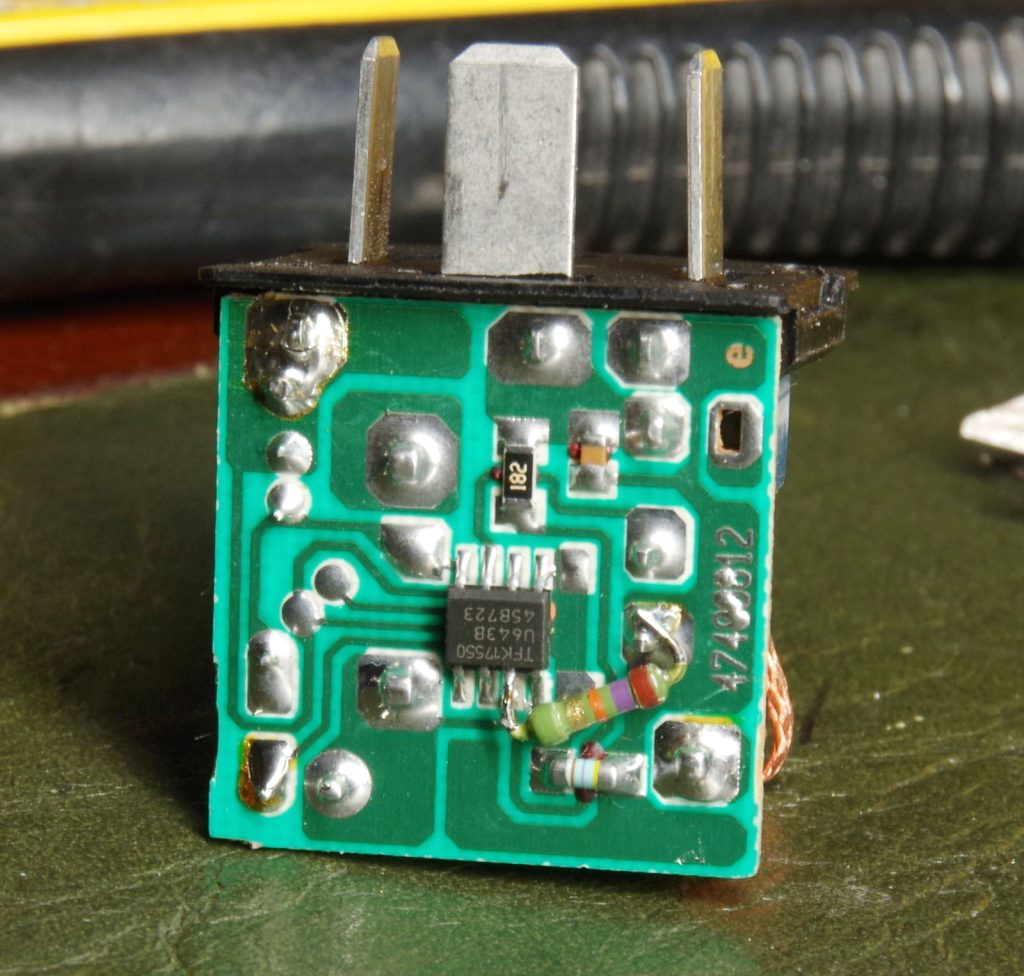
I don’t actually like leaving chip inputs open circuit as I always feel this is storing up problems for the future, so after unsoldering pin 7 I connected it to ground via a high value resistor as you can see in the photo below.

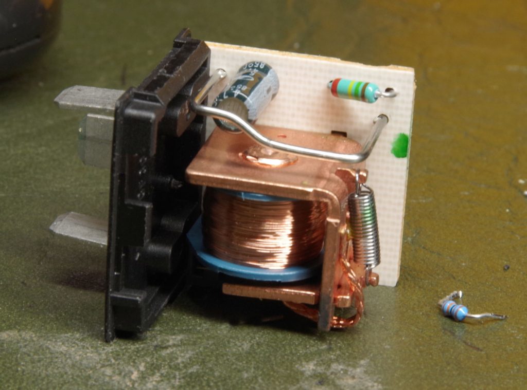
Having done this, I tested the flasher and it seemed to me that the flash rate was rather fast. Possibly it has always been like this and I haven’t noticed. Anyway, with the flasher available it seemed a sensible time to address the issue. I therefore replaced the timing resistor and reduced the flash rate to 80 flashes per minute which I think is not too far from the optimum 90 per minute.
In the photo below you can see the new resistor fitted. The wire loop was used as the current sense resistor.

Update: Although the indicators are working well, there is one other small problem. The dashboard indicator repeater lamp is now much dimmer than it used to be. This isn’t a serious problem as I never really look at it, but I suppose I’ll need to come up with a fix one day.